


YouTube
Tomos wiring harness
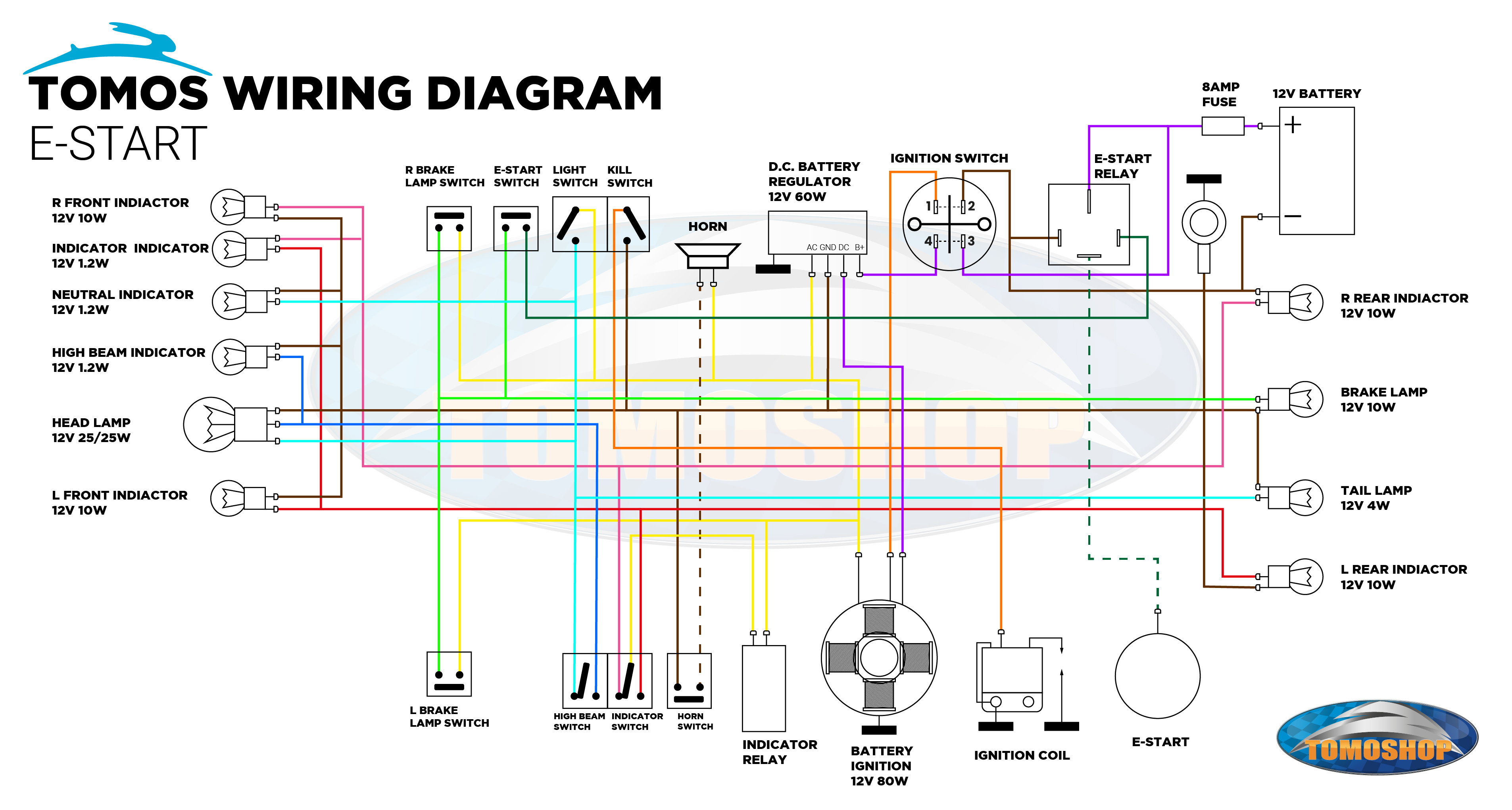
A Tomos wiring harness is an essential part of your Tomos. A Tomos wiring harness ensures that all components such as lighting, ignition, horn, switches and buttons receive electricity. If your wiring harness is broken, you'll notice it quickly because your lighting stops working or even your Tomos won't start anymore. But repairing a wiring harness can be challenging. Electricity isn't visible without a multimeter. Additionally, the existing wiring diagrams are hard to read. This makes wiring harnesses unclear for many people. That's why we've created these wiring diagrams for you! Below you'll find multiple versions showing only the wires you need for your specific harness. With these simple wiring diagrams, repairing your harness will be super easy.
Terms and symbols in a wiring harness
Terms
- Wiring harness: The complete set of wires and connectors in your moped.
- Ground: The metal frame of the Tomos serves as the "return path" for current.
- CDI: The ignition system that controls the spark plug via a coil.
- Ignition: Generates electricity through the running engine (for lighting and charging the battery).
- Voltage regulator: Regulates the voltage from the ignition to prevent overload.
- Fuse: Protects the circuit from short circuits (melts when current is too high).
- Continuity: An unbroken current path.
- Short circuit: Current flows directly from + to - without load.
- Relay: An electrical switch for heavy currents (e.g. starter motor).
Symbols
- V= (DC Voltage): Direct current voltage
- V~ (AC Voltage): Alternating current voltage
- Ω (Ohm): Resistance (e.g. measuring a wire or coil).
- ►⊢ (Continuity): An unbroken current path.
- A (Ampère): Current strength (e.g. current consumption of a lamp).
- ⏚ (Ground): Symbol for ground in diagrams.
The difference between series and parallel circuits
Series circuit
When components are connected in series, they form a continuous circuit - like a chain. Two important properties apply:
- Current is equal everywhere: the same current flows through each component (e.g. bulbs, resistors).
- Voltage divides: the total source voltage is divided across the components.
Problems with series circuits:
- One defect, everything fails: If one bulb breaks, the chain is broken and current stops.
- Unpredictability with different components: Imagine a 3V and a 9V bulb in series on 12V. The 3V bulb gets too much voltage (→ burns out), the 9V bulb too little (→ dims).
Applications: Old Christmas lights, circuits where components need the same current (e.g. ammeters in series).
Parallel circuit
In parallel circuits, components each have their own current path, like exits on a highway. The following applies:
- Voltage is equal everywhere: Each component gets the full source voltage (e.g. 12V).
- Current divides: The total current splits across the components.
Advantages and disadvantages of parallel circuits:
- Independence: A defective bulb doesn't affect the others. Other components keep working even if one is broken.
- Flexibility: You can add extra components without adjusting the voltage.
- Safer for power components: No risk of overvoltage.
- Disadvantage: Higher total current: More components = more current from the source (battery drains faster).
Applications: Household sockets, car lighting, USB hubs.
How to measure continuity and connections
A multimeter is a must-have if you want to repair or modify your wiring harness. Here's how to measure continuity and connections on your harness.
Step-by-step explanation
Multimeter settings:
Connect test leads:
Choose measurement points:
Results
Difference between continuity and short circuit
Tips for making a wiring harness
My bulbs keep burning out
If your bulbs (even new ones) keep burning out on your Tomos, this is almost always a sign of a defective voltage regulator. Here's a clear, comprehensive guide to test and fix this.
What does the voltage regulator do?
Function: It ensures the voltage doesn't get too high. If it's not working properly, the alternator delivers uncontrolled high voltage → bulbs and battery get too many volts → bulbs burn out or battery overcharges.
How to test a defective voltage regulator?
Multimeter settings:
Result:
Frequently asked questions (FAQ)
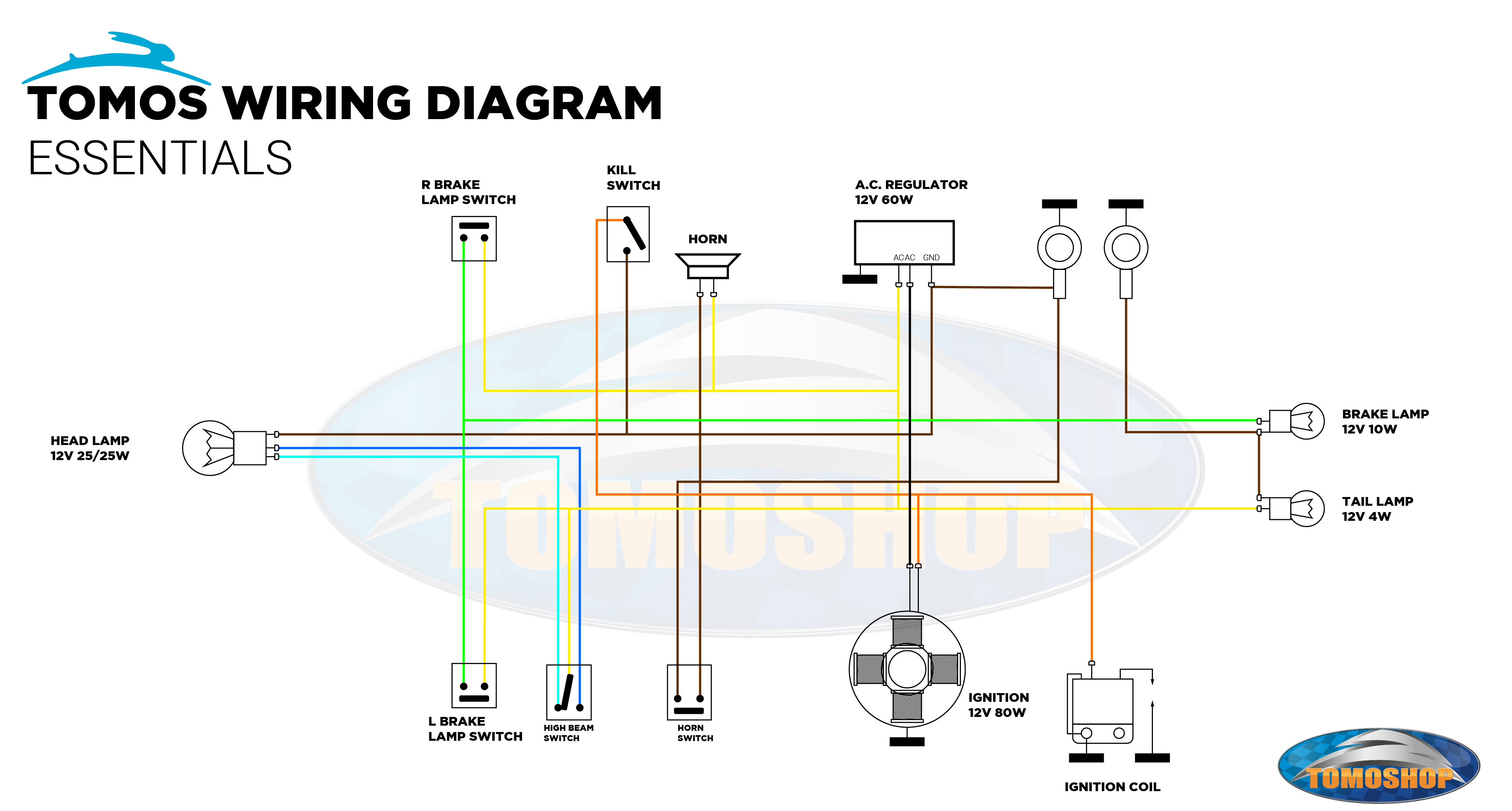
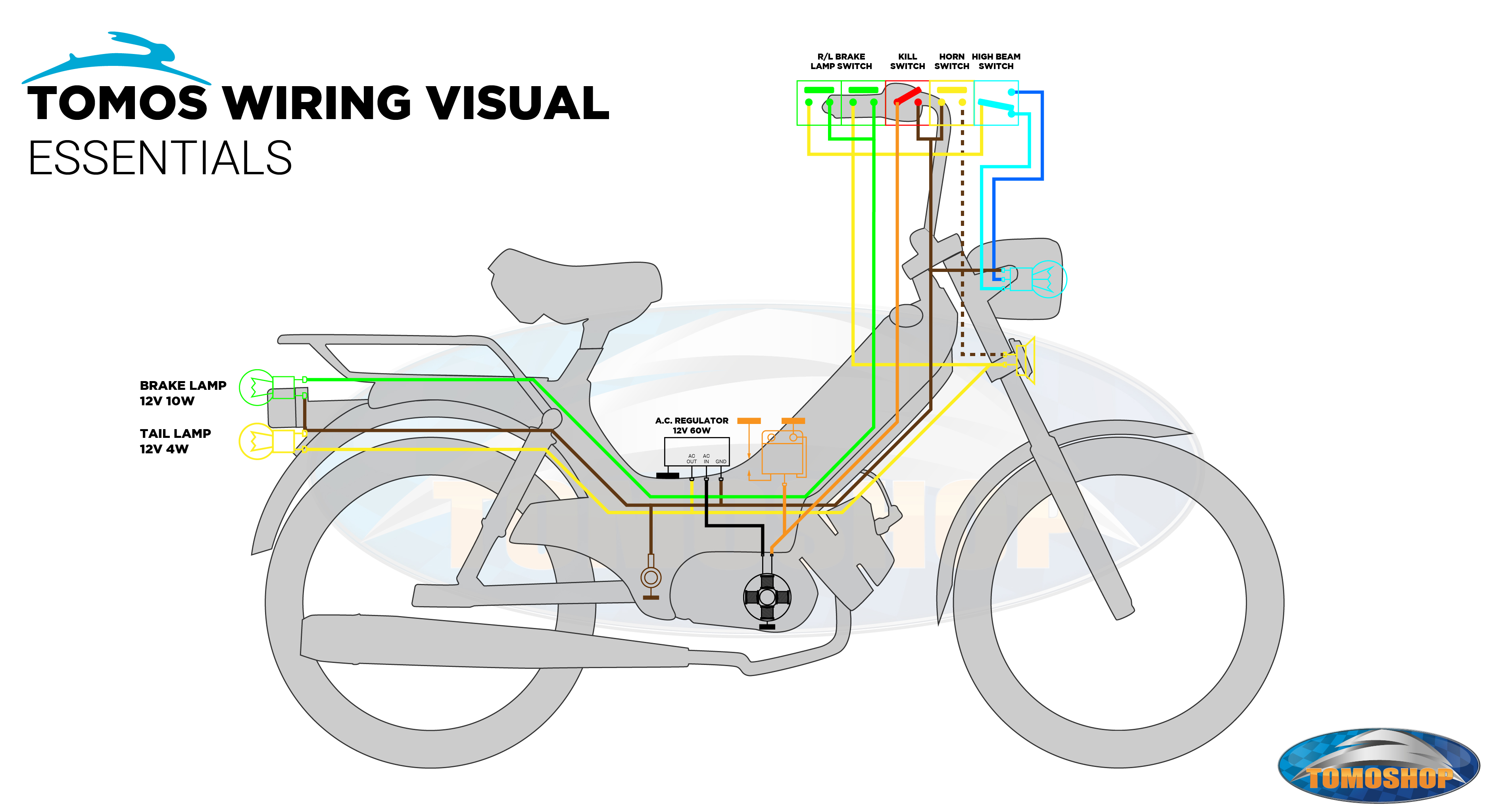
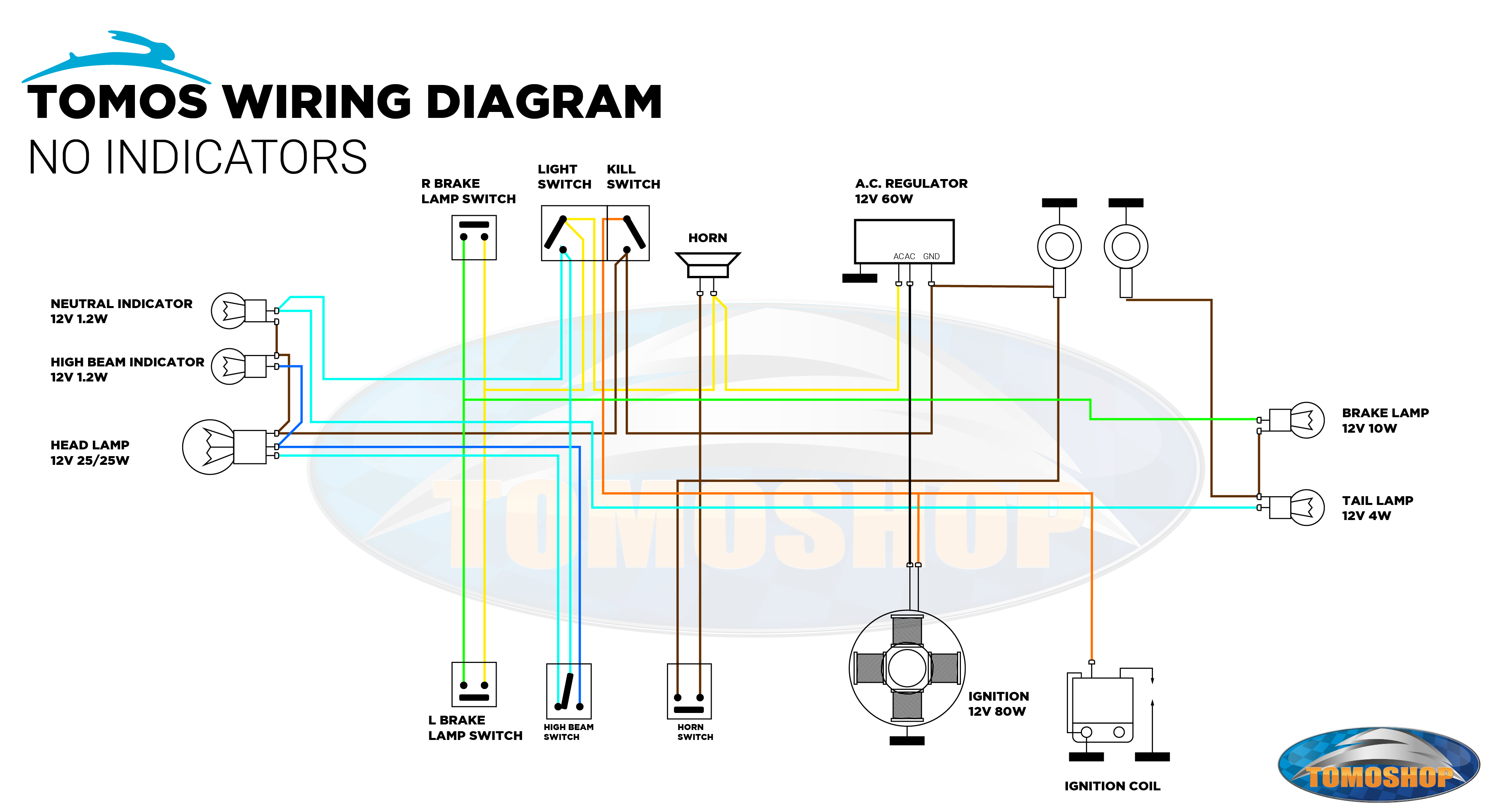
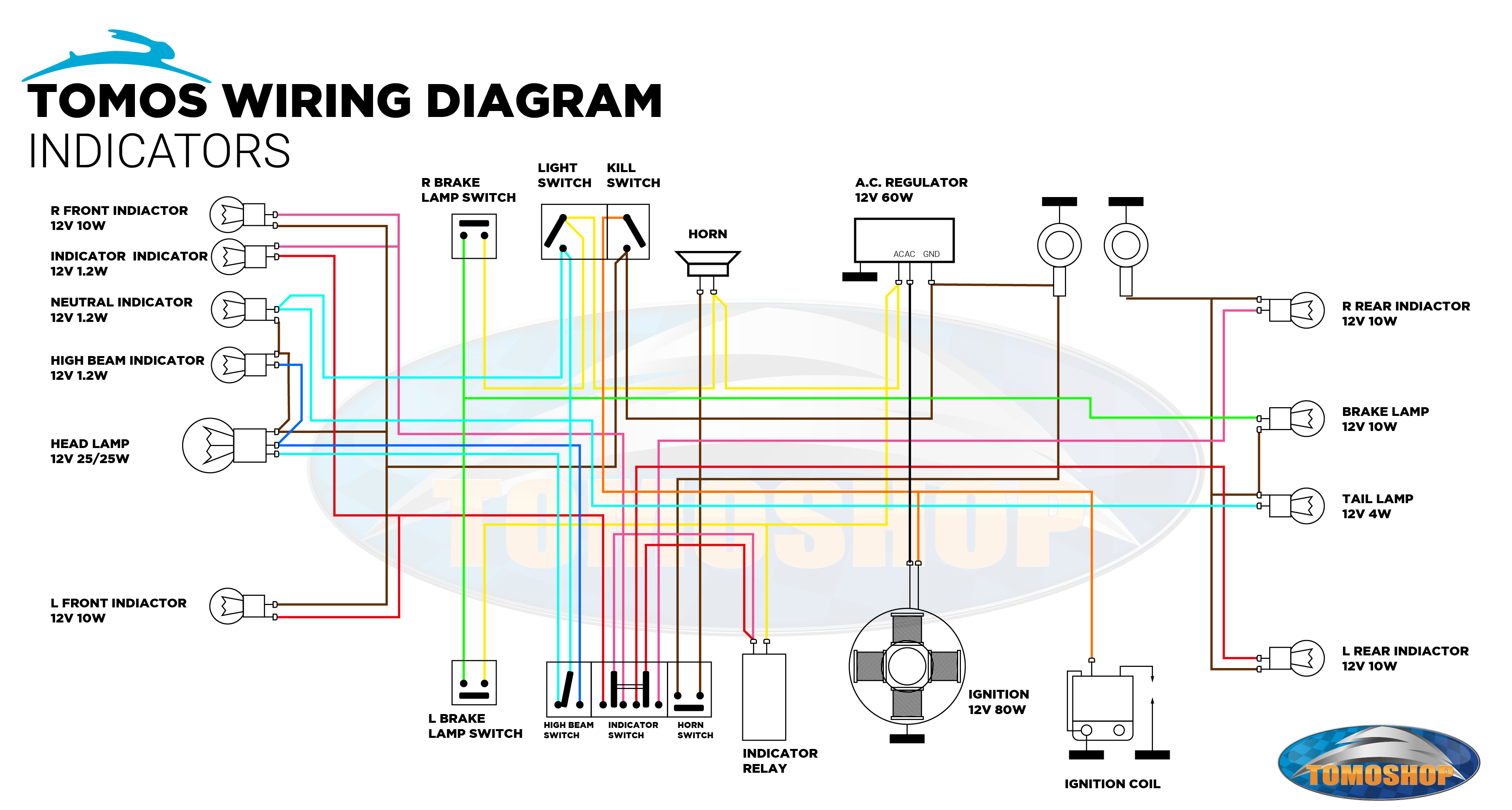
Wiring diagrams